| < 1912 | 1914 > |
Home | Paige-Detroit History | Specifications | My 1918 Paige | Cars/parts/information | Some Paige Autos For Sale 1962-98
Some Features of the Paige-Detroit Thirty-six
The Horseless Age Magazine
October 1, 1913, p. 541; Corrections October 22, 1913, p. 697
 |
| Engine |
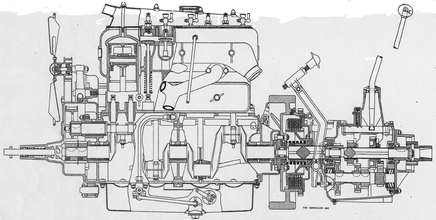
The car built by the Paige-Detroit Motor Car Co. of Detroit embodies a four-cylinder unit power plant, with three point support. The motor of this car is of the en bloc type, the bore being 4 inches and the stroke 5 [originally 4-1/4]. All the valves are located on the left-hand side of the cylinders, but the exhaust pipe is so designed that left-hand drive may be readily applied, despite the location of the valves. It is equally easy to apply right-hand drive for foreign trade on this car.
 |
| Engine Support |
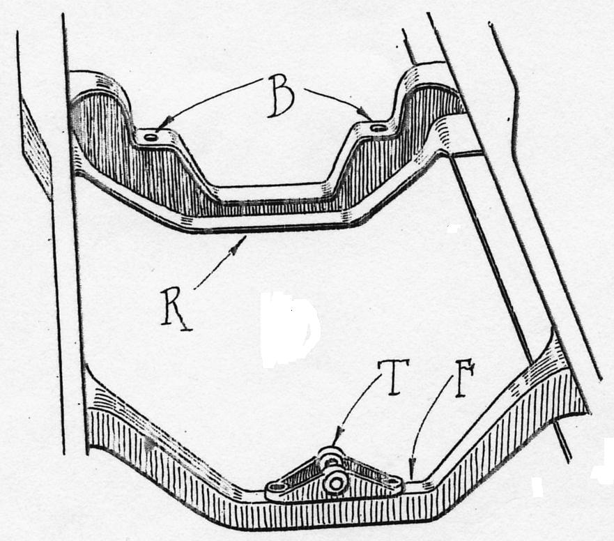
The method of supporting the power plant is shown in one of the sketches. Two studs project downward from box-section crank-case arms, and pass through two holes B in the frame cross member R. At the front of the motor a trunnion is fitted, which rests in the trunnion block T, the latter being fastened to the cross member of the frame F by means of a couple of bolts. Both frame cross members are deeply dropped in order to permit the oil pan to be readily removed from the crank case.
The valves are made in two pieces, the heads being cast [originally case] iron and the stems steel. They provide a clear opening of 1-13/16 inches, and have an outside diameter of 2 inches. The valve stems measure 3/8-inch in diameter and have 4-1/2-inch bearing in the guides.
The camshaft, the magneto and water pump and electric generator are driven by silent chains mounted on flanged wheels, the centre of which are non-adjustable. The crankshaft is a heavily webbed drop forging, and is mounted upon three main bearings. all of which are 1-3/4 [originally 1-3/8] inches in diameter.
Some interesting examples of pressed steel work are found on this motor. The big cover plate for the tops of the cylinder water jacket is made of pressed steel instead of a casting. The oil pan and reservoir are also made of pressed steel [and welded into one solid piece]. The cover plate is formed from a single piece of sixteen gauge steel, drawn into shape and held in place by four studs which screw into the tops of each cylinder, with acorn type nuts. The steel header is flanged at the bottom and a gasket is used to pack it. At the forward end a tube is welded into a lip extruded at the forward end.
The lower half of the crank case is pressed from No. 16 U.S. gauge sheet steel. It is made in two pieces, one serving as an oil container and the other as a splash basin. The flanges on the two pieces are placed one immediately above the other, so that the act of clamping the lower one onto the crank case serves to hold the upper one in place. The sump has a capacity of about four quarts of oil. The oil from the supply basins returns to the sump through three holes, the rearmost one of which is located between the third and fourth cylinders. Immediately beneath this hole is a baffle plate which extends well up under the second cylinder. The use of this baffleplate is claimed to eliminate smoking when climbing a steep hill, because it prevents the oil in the sump, should that be full, from rising in the rear splash basins. The oil pump is of the plunger type, and is operated by an eccentric located on the cam-shaft. This pump is 5/8-inch in diameter and has a 1/4-inch stroke. Two 7/16 [originally 3/8]-inch ball check valves are used. The pump is carried entirely in the upper portion of the crank case and is held in place by two bolts. Undoing two compression couplings and these two bolts permits the entire pump with the check valves to be removed from the motor. The oil strainer in the bottom of the sump is also readily removable, although it drains the oil reservoir when it is removed. The pump lifts oil from the sump and delivers it under pressure to a tube cast in the crank case. From this tube the oil is sprayed through a number of nozzles into the pockets provided above the main bearings and into the splash basins of the motors.
Bosch single [originally Splitdorf dual] ignition is standard equipment on these models. Battery ignition is provided to facilitate starting in cold weather.
 |
| Radiator Bracket |
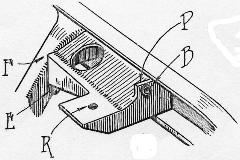
The cooling system comprises a pump and cellular [originally vertical tube] type of radiator. The pump shaft is extended in either direction, and carries a pulley at one end which drives the six-blade, 16-inch pressed steel fan, and the magneto at the other. This ball bearing fan is driven at 1-83 times engine speed. The pump is said to float, inasmuch as it is not securely fastened but takes its bearing upon the shaft. A leather coupling is provided between the magneto and the pump in order to provide for any slight disalignment. The radiator is supported upon a pair of malleable cast iron brackets, which are inserted in the side rails of the frame. Two studs passing through the holes R serve to hold the radiator in place. The casting is riveted in place, one of the rivets being shown at E, where it is fastened onto the front cross member of the frame. A hard rubber bushing B is inserted as shown, to insulate and prevent the head lamp wire from chafing on the metal.
 |
| Lamp Bracket |
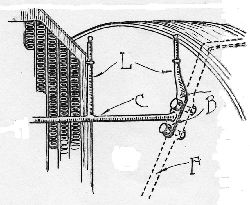
Five electric lamps are part of the equipment. The head lamp bracket is bolted onto the front fender irons F by a couple of three-eighths inch bolts B. The lamp iron is made up of a number of drop forgings. The right hand prong L and plate for the bolts, and a portion of the cross piece C, are forged in one piece. The left hand prong L is forged in the form of a T. When the two pieces are welded together on the horizontal piece C they assume the form shown in the sketch.
The selective transmission, which gives three forward speeds and reverse, is carried by means of a couple of arms of box section which surround the 16-inch flywheel. The multiple disc clutch is made up of fourteen saw steel plates, seven of which are three-sixteenths inch thick, the others one-sixteenth inch. Each of the former carries thirty-two seven-sixteenths inch cork inserts. The inside and outside diameters of this clutch are 7 and 9-1/2 inches, respectively.
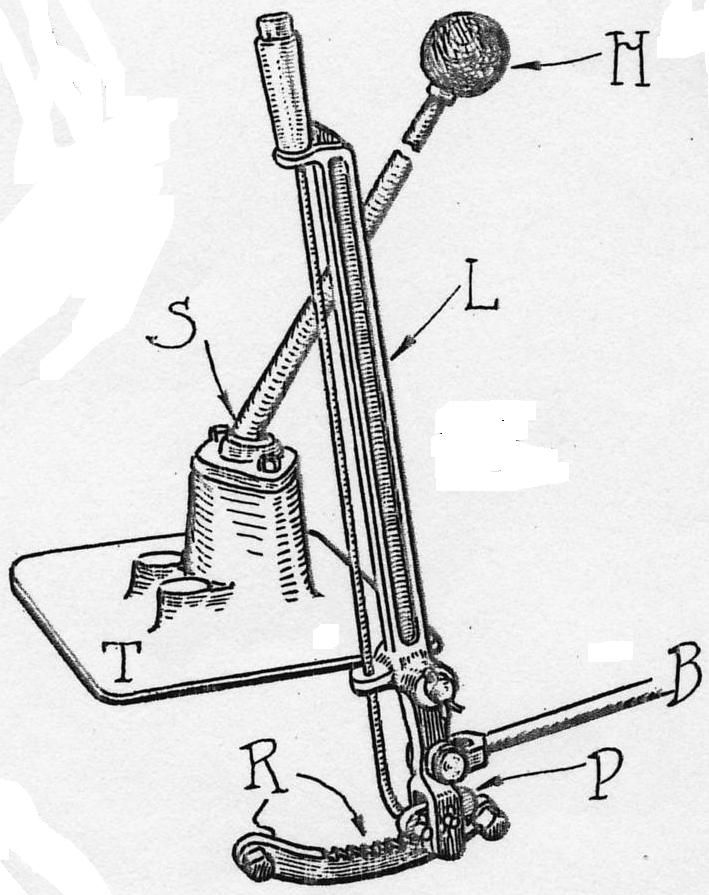 |
| Gear and Brake Levers |
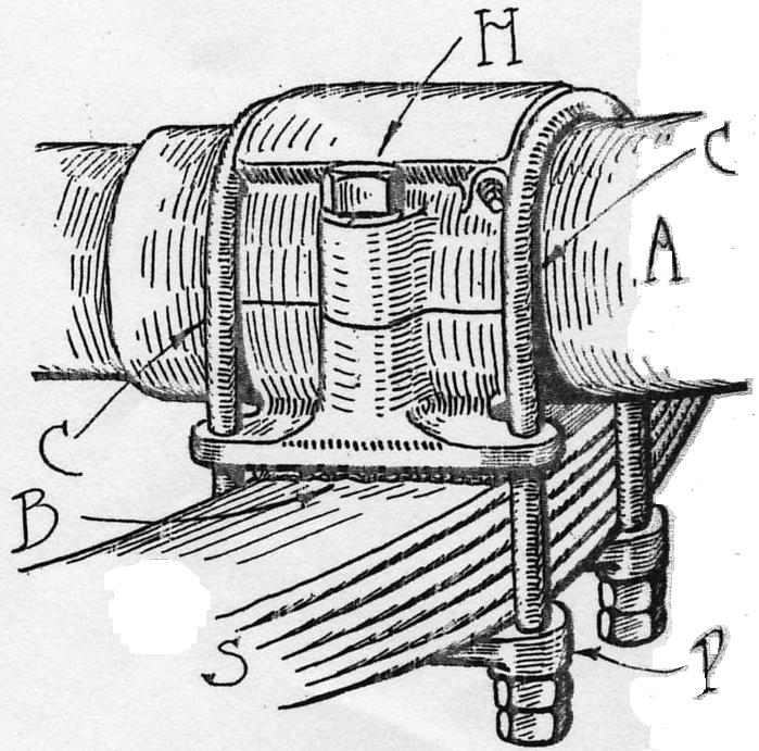 |
| Rear Spring Mounting |
The arms which support the transmission also serve to carry the pedals. They have been designed in such a manner that right or left hand drive may be applied to the car by the change of one pedal only. This also applies to the steering gear and self starter mechanism, all frames being machined so as to carry either right or left band drive. The transmission has 6-8 stub tooth gears with seven-eighths inch face. The shifter forks and selectors are mounted in the top of the transmission case. The gear shift lever H is mounted in a ball and socket joint S, which is formed in the cover plate T of the transmission. The lever is inclined to the rear, so that it comes up to the driver's hand very conveniently. A pin is attached to the transmission cover plate T, upon which the emergency brake lever L is pivoted. The emergency brake pull rod is indicated at B. A pawl P locks the brake after it has been applied. The ratchet R in which this pawl engages is placed below instead of above the pivot of the emergency brake lever.
Full elliptic springs are used at the rear and semi-elliptic in front. These in the rear are pivoted in a bracket attached to the frame, and pass under the axle, to which they are clipped, as shown in the sketch. The U-clips, as shown at C, are employed. The spring seat is split, and held together by a pair of cap screws H. It is rotatably mounted onto the axle tube A. The spring S is clamped between a plate P and the spring seat. Some cotton fabric B is placed between the spring seat and the spring.